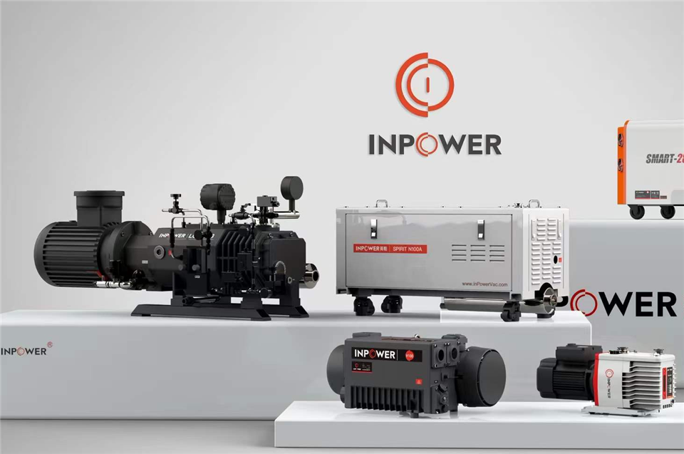

Even a well-built vacuum pump will underperform if it is connected to poorly designed piping. Undersized lines, leaking joints, and trapped condensate lead to slow pump-down, unstable ultimate pressure, oil contamination, and premature wear of vanes and rotors. So what are the vacuum pump installation piping requirements you should follow? This guide breaks them down by function: general rules, inlet piping, exhaust piping, cooling water connections, material selection, and final leak checks.
Why piping design matters for vacuum systems
Unlike water or compressed-air lines, vacuum piping works against a pressure difference of at most one atmosphere, so every unnecessary bend, restriction, or leak has an outsized effect on performance. A long, narrow line acts as a throttle between the chamber and the pump: the pump may reach its rated ultimate pressure at its own inlet while the process chamber never gets close. Good piping protects three things at once: pumping speed, ultimate vacuum, and the service life of the pump itself.
General piping requirements
Pipe diameter: the nominal diameter of the connecting pipeline must not be smaller than the pump's suction port. For long runs, step up one size to compensate for conductance losses.
Routing: keep pipelines as short and straight as possible. Minimize the number of elbows, and use long-radius bends instead of sharp 90-degree fittings.
Sealing: every joint between the pump and the system must be reliably sealed. Even a pinhole leak that is negligible in a pressure line can dominate the gas load of a vacuum system.
Cleanliness: when welding pipes, remove all welding slag, scale, and debris from the inside of the pipeline before connecting it to the pump. Slag drawn into the pump chamber will score vanes and rotors.
Support: support the piping independently so that no pipe weight or thermal stress is carried by the pump casing. A short flexible bellows near the pump inlet isolates vibration and makes alignment easier.
Inlet (suction) piping requirements
The inlet line has the greatest influence on achievable vacuum, and it deserves the most attention during installation.
Size the line at least equal to the pump inlet port. When two or more pumps are piped in parallel, size the common header close to the sum of the individual inlet areas.
Slope horizontal runs so that any condensed liquid drains away from the pump, and install a drip leg or condensate trap at low points where vapor condensation is expected.
Fit an isolation valve and a vacuum gauge directly above or near the pump inlet. This lets you blank off the system and verify the pump's own ultimate pressure during commissioning and troubleshooting.
Install an inlet filter when the process gas contains dust or particles, and use chemically compatible filtration when the gas is reactive or corrosive.
If a solenoid valve is mounted at the inlet, wire it so that it opens and closes together with the pump motor. This prevents oil suck-back into the piping when the pump stops under vacuum.
Practical tip: a pump that cannot reach its rated ultimate pressure is very often blameless. Blank off the inlet and test the pump alone before dismantling anything; if the pump is fine, the leak or restriction is in the piping.
Exhaust piping requirements
Exhaust piping is frequently treated as an afterthought, yet it directly affects oil temperature, noise, and the working environment.
Keep the exhaust line short and at least as large as the exhaust port. Excessive back pressure raises oil temperature, increases power consumption, and can push oil mist past the seals.
Slope the exhaust line toward a separator or drain point so that condensed oil and vapor cannot flow back into the pump after shutdown.
Never submerge the exhaust outlet in liquid, and avoid long vertical risers without a drain at the bottom.
If the exhausted gas affects the working environment, pipe it outdoors or fit an oil mist filter at the exhaust port to recover oil and keep the air clean.
For an oil sealed rotary vane vacuum pump, check the exhaust line regularly during the first weeks of operation; oil carry-over in the exhaust is an early warning sign of overfilled oil or excessive back pressure.
Cooling water and auxiliary piping
Water-cooled pumps and units add a second piping circuit that must be installed with the same care.
Connect the cooling water supply and return exactly as specified on the motor nameplate and product manual, and fit shutoff valves on both lines for maintenance.
Install a strainer on the supply side to keep rust and scale out of the cooling jacket, and arrange the return line so flow can be observed or metered.
Keep the inlet water temperature and pressure within the limits in the manual; water that is too warm or too weak in flow lets the oil overheat and degrade quickly.
In freezing conditions, drain all cooling water from the pump after shutdown to prevent the chamber or jacket from cracking.
Material selection by pump type and process gas
The right piping material depends on both the pump size and the gas being handled.
Smaller pumps: metal piping with oil-resistant rubber gaskets is the usual choice; it is rigid, durable, and easy to seal.
Larger pumps: vacuum-rated hose is acceptable for flexible sections, but ordinary plastic or thin rubber hose must be avoided because it collapses or permeates under vacuum.
Corrosive duty: for chemical, pharmaceutical, and lithium-battery processes, use stainless steel or other compatible materials, and match the pump itself to the duty. Industrial dry vacuum pumps with oil-free screw mechanisms, including titanium-alloy versions for corrosive gases, remove oil from the process side entirely and simplify exhaust treatment.
High-vacuum duty: for Roots and turbo pump combinations, keep every upstream joint metal-sealed where possible, because elastomer permeation becomes part of the gas load at low pressures.
Leak testing and final checks before startup
Before the first run, walk the whole line and verify the following points.
Leak-test the assembled piping with the pump blanked off; check every flange, gasket, threaded joint, and weld.
Confirm that all welding slag and installation debris has been flushed or cleaned from the line.
Verify that the isolation valve, vacuum gauge, inlet filter, and condensate trap are installed and in the correct positions.
Check that piping supports carry the line weight and that the flexible section near the pump is not under tension or compression.
Record the blanked-off ultimate pressure as a baseline; it makes later troubleshooting far faster.
Conclusion
In short, the core vacuum pump installation piping requirements are: a pipe diameter no smaller than the pump port, short and straight routing, a clean and debris-free interior, reliably sealed joints, proper slope and drainage on both inlet and exhaust lines, suitable filtration, and isolation valves with a vacuum gauge for monitoring. Getting these details right at installation time costs little and pays back through faster pump-down, stable vacuum, and a longer pump life.
InPowerVac, the vacuum equipment brand of Zhejiang Yingpa Electromechanical Co., Ltd, manufactures rotary vane, Roots, turbo, and dry screw vacuum pumps together with inlet filters, oil mist filters, and other vacuum components, and provides customized vacuum pump systems for special applications. If you are planning a new installation or upgrading an existing line, the InPowerVac engineering team can help you match the pump and the piping layout to your process.