
Processes such as plasma etching, mass spectrometry, vacuum coating, and heat treatment rarely stay inside a single flow regime. On every pump-down, and often during the process itself, chamber pressure sweeps through the transitional range between viscous and molecular flow. A pump that looks ideal on a datasheet at 10-7 mbar can behave very differently at 10-2 mbar. So how does a low pressure vacuum turbo, meaning a turbomolecular pump, really compare with a molecular drag pump in this in-between band? The answer comes down to how each machine moves gas, and where along the pressure scale each mechanism runs out of leverage.
What the transitional pressure range actually means
Vacuum engineers classify gas flow by the Knudsen number, the ratio of the molecular mean free path to a characteristic dimension of the system. In practical terms for typical chamber and pipe sizes:
- Viscous (continuum) flow sits roughly above 10-1 mbar. Molecules collide mostly with each other, and the gas behaves like a fluid.
- Molecular flow sits roughly below 10-3 mbar. Molecules collide almost exclusively with the walls, and each molecule travels independently.
- Transitional (Knudsen) flow is the decade in between, roughly 10-3 to 10-1 mbar, where both collision types matter and neither simple model fully applies.
This middle band is exactly where many industrial processes either dwell, as in plasma and drying applications, or must pass through on every cycle. Pump behavior here is not a simple average of the two extremes, which is why the turbo-versus-drag question deserves a careful answer.
How a low pressure vacuum turbo works
A turbomolecular pump is a multi-stage axial-flow turbine. Rotor blades spinning at tens of thousands of revolutions per minute strike gas molecules and bias their motion toward the exhaust. Stage after stage, the gas is compressed until a backing pump can carry it to atmosphere.
This design is outstanding in molecular flow. A bladed turbo vacuum pump routinely reaches ultimate pressures in the 10-7 to 10-10 mbar class, holds a high compression ratio for heavy gases, and delivers a clean, oil-free vacuum on the inlet side. That is why turbos dominate in analytical instruments, semiconductor load locks, and research chambers.
The transitional range is where the bladed rotor starts to lose its edge. As pressure rises and intermolecular collisions become frequent, molecules knocked toward the exhaust get scattered back into the inlet. Pumping speed and compression both sag, power draw and rotor heating climb, and the pump depends heavily on its backing line to keep the foreline pressure low, typically well below about 1 mbar for a purely bladed rotor.
How a molecular drag pump works
A drag pump abandons blades altogether. Instead, a smooth, fast-spinning cylinder or disk drags gas along a narrow channel by molecular friction. The two classic geometries are the Holweck stage, with helical grooves wound around a rotating cylinder, and the Siegbahn stage, with spiral grooves cut into a disk.
Because the pumping channel is a confined corridor rather than an open blade row, the drag mechanism keeps working as the gas becomes denser. Drag stages remain effective through the molecular regime and deep into transitional flow, and they can exhaust against foreline pressures that would stall a bladed stage, commonly up to about 10 mbar in compound designs. That tolerance translates directly into a smaller, cheaper backing pump, sometimes even a diaphragm unit.
The trade-off is that a drag stage moves less gas per unit of inlet area and, on its own, does not reach as deep an ultimate pressure as a bladed turbo. Its compression ratio for light gases such as hydrogen and helium is also weaker than that of a well-designed blade row.
Head-to-head in the transitional pressure range
| Aspect | Low pressure vacuum turbo (bladed) | Molecular drag pump (Holweck / Siegbahn) |
|---|---|---|
| Peak efficiency regime | Molecular flow, below about 10-3 mbar | Molecular flow through transitional flow |
| Behavior in the transitional band | Pumping speed and compression fall off as collisions scatter gas back | Comparatively stable; the channel keeps dragging gas forward |
| Tolerable foreline pressure | Low; a purely bladed rotor usually needs the foreline well below about 1 mbar | High; drag stages commonly exhaust against up to about 10 mbar |
| Backing pump size | Larger two-stage rotary vane or scroll pump | Smaller backing pump; diaphragm pumps often sufficient in compound designs |
| Ultimate pressure with backing | 10-7 to 10-10 mbar class | Not as deep as a bladed turbo on its own |
| Compression of light gases (H2, He) | High | Lower than bladed stages |
| Tolerance of gas-load bursts | Sensitive; speed and compression dip under sudden load | Tolerant; suited to steady throughput in the transitional band |
Which one should you choose?
Match the machine to where your process actually spends its time:
- Choose a bladed turbo when the working point sits deep in molecular flow and the transitional band appears only as a brief pump-down transient. You get the deepest ultimate vacuum, the strongest light-gas compression, and the cleanest inlet conditions.
- Choose drag stages when the process dwells in the transitional band or pushes a continuous gas throughput. The higher foreline tolerance lets you shrink the backing pump and cut both capital and running costs.
- When in doubt, look at gas species and duty cycle. Light gases and ultra-high vacuum goals favor blades; heavy throughput and rougher forelines favor drag geometry.
The practical answer: compound pumps
Modern vacuum engineering rarely forces an either-or decision. A compound or hybrid molecular pump mounts bladed turbo stages near the inlet and drag stages near the exhaust on the same rotor. The blades deliver the deep ultimate vacuum and light-gas compression; the drag section absorbs the transitional-flow load and raises the tolerable foreline pressure, so a smaller backing pump finishes the job. This is why compound designs have become the default choice for plasma tools, furnaces, and differentially pumped mass spectrometers.
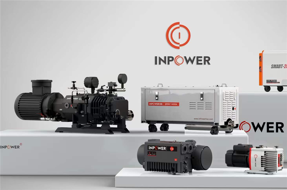
InPowerVac builds this thinking into its product line. The Low Pressure Vacuum 10-7 Mbar Turbo reaches the 10-7 mbar class for demanding high-vacuum work, while matched front-stage rotary vane pumps handle the backing duties. Whether you need a standalone high vacuum turbo pump or a complete turbo pump system sized for a transitional-pressure process, the InPowerVac engineering team can configure the right combination for your chamber, gas load, and duty cycle.
The bottom line: a low pressure vacuum turbo wins on ultimate vacuum and light-gas compression, while a drag pump wins on transitional-flow stability and foreline tolerance. Know your working pressure band, and the right choice, or the right hybrid, usually reveals itself.