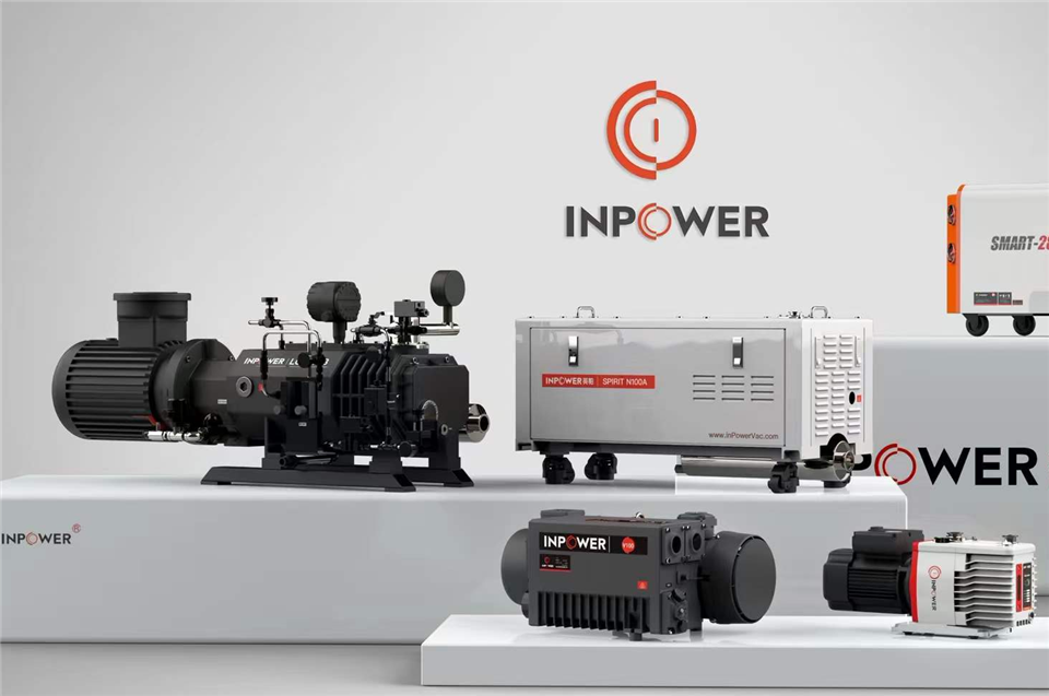

Inside every mass spectrometer, sputtering coater, and high-vacuum furnace that reaches into the 10-7 mbar range, a rotor is spinning faster than a jet engine turbine — typically 30,000 to 90,000 revolutions per minute. That rotor is the heart of a turbo molecular pump, and when it fails, it rarely fails quietly: a single mistimed power cut can turn a precision instrument into scrap in seconds. This guide explains how the pump actually works, why it can never run alone, where it earns its keep, and how to protect it from its most destructive enemy — oil backstreaming.
How a Turbo Molecular Pump Actually Works
At the pressures where a turbo molecular pump operates, gas is in the molecular flow regime: the mean free path of a molecule is longer than the distance between pump surfaces, so molecules almost never collide with each other — only with the walls and the rotor. The pump exploits this behavior directly. Multiple rows of inclined blades, machined to tight tolerances, sweep past matching stator rows. A gas molecule that drifts into the inlet is struck by a blade surface moving at hundreds of meters per second and is knocked preferentially toward the exhaust. Stage after stage, this momentum transfer builds compression.
Two consequences follow from this physics. First, compression ratio depends on molecular weight: a turbo molecular pump compresses heavy hydrocarbon molecules by many orders of magnitude, but is far less effective against hydrogen and helium. That is why high-vacuum systems that handle light gases must pay close attention to stage design and foreline conditions. Second, the pump is inherently hydrocarbon-free at the inlet when properly engineered — which is precisely why analytical instruments and semiconductor tools depend on it. A well-designed system with an appropriate backing arrangement reaches the 10-7 mbar class, such as the low-pressure turbo models in the InPowerVac turbo pump range.
Bearing architecture is the third design variable. Grease-lubricated ceramic bearings are economical and allow any mounting orientation, but the grease has a finite service life. Magnetically levitated rotors eliminate mechanical contact almost entirely, extending maintenance intervals at a higher purchase price. The right choice depends on duty cycle, orientation constraints, and how painful unplanned downtime is in your process.
Why a Turbo Molecular Pump Never Works Alone
A turbo molecular pump cannot start at atmospheric pressure and cannot exhaust against it. Its blades only gain traction once gas is thin enough to behave molecularly, so a backing pump must first rough the chamber and then hold the foreline in the rough-vacuum range while the turbo runs at full speed. The pairing decision shapes everything downstream: ultimate pressure, cleanliness, tolerance of solvent vapor, and maintenance cost.
- Two-stage rotary vane vacuum pump: the classic, cost-effective backing choice for analytical benches, leak detectors, and research systems. It reaches deep rough vacuum and tolerates intermittent solvent loads when the gas ballast is used correctly. Dedicated front stage vacuum pumps are built exactly for this backing role.
- dry screw vacuum pump: the preferred backing pump where oil vapor cannot be tolerated at all — semiconductor, lithium battery, and chemical processes — or where the process itself is corrosive or particle-laden.
Sizing rule of thumb: the backing pump must keep foreline pressure below the turbo pump's critical backing pressure at your maximum gas load, not just at no-flow. Undersizing here is one of the most common and least diagnosed causes of "mystery" high-vacuum instability.
Where Turbo Molecular Pumps Earn Their Keep
Because they deliver deep, clean, hydrocarbon-free vacuum in a compact package, turbo molecular pumps sit at the core of several demanding fields:
- Analytical instruments: LC-MS, GC-MS, and electron microscopes, where ion optics and quadrupoles demand a clean 10-3 Pa and below environment.
- Semiconductor and photovoltaics: load locks, transfer chambers, and process modules where particles and oil vapor destroy yield.
- Surface coating and vacuum metallurgy: PVD chambers and furnaces that cycle repeatedly to high vacuum.
- Research and leak detection: accelerators, beam lines, helium leak detectors, and university vacuum benches.
The Silent Killer: Oil Backstreaming
Ask field service engineers what destroys turbo molecular pumps and their host instruments, and one answer comes back repeatedly: oil mist traveling backward from the backing pump. In normal operation, the net gas flow from the turbo outlet toward the foreline acts as a gas-dynamic barrier that keeps backing-pump oil vapor from diffusing upstream. Three situations collapse that barrier:
- Sudden power loss with a stuck anti-suckback valve. The backing pump rises toward atmospheric pressure while the turbo's inlet is still deep in high vacuum. The pressure gradient reverses instantly, and the still-spinning rotor acts like a vacuum cleaner, pulling oil vapor back through the foreline at high velocity.
- Degraded backing-pump oil. vacuum pump oil that has absorbed water and solvent (acetonitrile from LC-MS benches is a classic) shows a sharply higher vapor pressure. Even in steady operation, that elevated oil vapor pressure can overcome the turbo's compression ratio for heavy molecules and creep upstream by diffusion.
- Improper venting habits. Venting by simply cutting power, or venting the foreline before the rotor has slowed, recreates the reversed gradient deliberately.
The damage is twofold. Oil film on a rotor turning at tens of thousands of rpm unbalances it; at these speeds a tiny mass asymmetry can escalate into blade contact and total rotor destruction. And oil molecules that reach the process chamber deposit as an insulating hydrocarbon film — on quadrupoles and ion guides in a mass spectrometer, or on substrates in a coater — that no amount of source cleaning will fully reverse.
Field-proven prevention routine:
- Always shut down through the controller sequence: cut turbo drive, wait for the rotor to drop below its safe threshold, then vent with dry, clean nitrogen. Never vent by pulling the plug.
- Run the backing pump's gas ballast for 15–30 minutes weekly when the process involves water or solvent vapor, purging contaminants from the oil.
- Change backing-pump oil at the first sign of amber discoloration or emulsification, and investigate any new gurgling or labored sound at startup.
- Fit and maintain an oil mist filter on the exhaust line, and verify the anti-suckback valve at every service interval.
How to Specify a Turbo Molecular Pump: A Buyer's Checklist
| Parameter | What to Check | Why It Matters |
|---|---|---|
| Pumping speed (L/s) | Rated speed at the inlet flange for N2, matched to chamber volume and process gas load | Undersized pumps extend pump-down time and never reach specification under load |
| Ultimate pressure | 10-7 mbar class with appropriate backing pump and clean, baked system | Defines the ceiling for analytical and UHV-leaning work |
| Compression ratio for H2/He | Published values for light gases, not just nitrogen | Critical for processes outgassing hydrogen or using helium carrier gas |
| Inlet flange | ISO-K for general high vacuum; CF (ConFlat) where bakeout to true UHV is required | Determines achievable base pressure and chamber compatibility |
| Bearing type | Grease-lubricated ceramic vs. magnetically levitated | Trades purchase cost against maintenance interval and orientation flexibility |
| Critical foreline pressure | Maximum tolerable backing pressure at full throughput | Dictates the minimum backing pump size and foreline trap design |
| Controller and interfaces | Ramp control, vent valve logic, gauges, remote I/O | The controller is your first line of defense against backstreaming events |
Why Source from a Factory That Builds the Whole Vacuum Chain
A turbo molecular pump is only as reliable as the rotor inside it — and as the backing pump beneath it. Zhejiang Yingpa Electromechanical Co., Ltd, the company behind the InPowerVac brand, has specialized in vacuum equipment since 2000 and operates as a Turbo Pump Manufacturer with the supporting chain under one roof: the turbo vacuum pump itself (including 10-7 mbar class models and complete turbo pump systems), the rotary vane and dry screw backing pumps to feed it, and the oils, filters, and spare parts that keep it alive.
That depth shows in the hardware. The company runs 92 sets of processing equipment — 30 of them imported, including 32 Mazak machining centers — and backs machining with a dynamic balance laboratory, a dedicated vacuum testing room, and three-coordinate metrology. For a component that spins at tens of thousands of rpm, dynamic balancing and full vacuum testing are not marketing bullet points; they are the difference between a rotor that survives a decade and one that fails in a quarter. It is the same manufacturing discipline that has made InPowerVac a supplier to Foxconn, Huawei, Samsung, and Tata Group, supported by two production bases in Zhejiang and Hebei and a 70,000 m² plant added in Taizhou in 2023.
Specifying a high-vacuum system? Send the InPowerVac engineering team your chamber volume, target pressure, gas load, and process chemistry, and receive a matched proposal — turbo pump model, backing pump pairing, and foreline accessories — directly from the factory. Contact Winnie at Winnie@inpowervac.com or call +86 13858602188 to start the conversation.